|
Gas generation measurement |


|
University of Padua IMAGE Department |
|
Actual landfill gas yields • The specific methane production rate expressed as m3CH4 per tonne may vary substantially from landfill to landfill owing to variations in waste composition, moisture content, microbial activity in the waste and supposedly also according to the age of the waste as a measure of the stability of the organic matter present in the waste • Observed methane production rates at actual landfills may vary owing to different efficiencies of the gas extraction systems, which may be influenced by the shape of the landfill, the top cover, the type of extraction system and the pumping rate applied Gas generation measurement • Field testing of landfills to determine present gas generation rates or long-term gas production potential is difficult and inexact, subject to problems in obtaining reliable data but also to problems stemming largely from the inherent heterogeneity of a landfill • The best approach is to use several different techniques • One technique is to try to simulate the landfill by enclosing portions of the landfill or a simulated landfill in a test volume in order to measure the gas generated (lysimeter testing) • A more common testing procedure is to pump gas from the landfill, measuring the amount and composition but also attempting to delineate the volume of the landfill giving rise to the gas being collected • Yet another concept is to measure gas passing into the atmosphere (flex testing) • Lastly, it is possible to measure gas generated by samples of refuse taken directly from the landfill and placed in containers (anaerobic sampling) Lysimeter testing • Laboratory scale: tipically, fresh refuse is placed in bottles, in columns or specially built containers. Water is added periodically, or leachate is recirculated, to provide adequate moisture and moisture flow to promote decomposition. Tubing is used to direct gas from the container to any of several types of gas measuring device. • Field scale: the concept is to build test cells of virtually any size manageable. The cell is tipically lined with clay and plastic film and is covered with a plastic film and/or compacted wet clay to avoid gas flow direct to the atmosphere. Advantages: • In theory, 100% of the gas can be collected and measured by either laboratory or field test cells • The process gives data regarding gas generation rates over a period of time, so that it is possible to follow decomposition patterns and gas generation changes over as a lond a period as desired • It is possible to use different conditions and different refuse compositions to determine the effects on gas generation Disadvantages: • It is very difficult to mimic real-world landfill conditions, and therefore it is very difficult to apply the results to full-scale landfills • The test cell does not provide the intermix of different decomposition stages and states of decomposition as is the case in the real-world landfill; therefore, for example, it is common to observe acid souring, which can reduce, postpone, or even virtually eliminate methane generation • It is also possible to get a great variety of results, many of which are not observed in real-world landfills Landfill gas pump tests • The overall concept is to withdraw gas from the landfill using the gas withdrawal system, and then to determine the volume of landfill from which the measured gas is withdrawn so one can project these rates to other portions of the site or to other landfills • Gas wells are used to withdraw the gas, and probes to measure the volume of landfill from which gas is withdrawn • In performing a pump test, it is necessary to determine background pressures with the well capped or not not being pumped • The most difficult part in gas testing is to determine the specific gas generation rate (the volume of gas or methane produced per tonne of refuse per day) or the radius or volume of influence of a well • This information is important for well field design and to determine the total extractable gas flow for full-scale gas withdrawal programmes • Wells should be placed at different parts of the landfill so the locations are representative of the entire landfill considered for gas withdrawal Standard vertical well • A typical well design consists of 120-150 mm nominal bore (NB) mineral-based polypropylene well casing inserted within a borehole within the waste, with the annulus filled with pea gravel • The top 4 m of the annulus are sealed using polyurethane foam or bentonite clay • The casing is slotted (3 mm) for the length inserted within the gravel pack • A wellhead made up of UPVC fittings enables the installation of a valve for fine-tuning the suction on each well, a sampling point to enable the well to be dipped for leachate, and a manometer to allow the wellhead suction to be measured • A length of flexible pipe is used to connect the wellhead to the collection pipework to allow for a different settlement rate between the two ones • This is the most easily installed well, particularly if the waste is at final restoration levelsvertical wells tend to settle at a different rate to the upper layers of waste surrounding them as they are subject to reducind settlement rates with increasing depth, creating a “floatation” effect • The installation must allow the well casing to “rise” above the surrounding ground level without damaging pipework and fittings or end-loading the casing • A well casing too highly loaded, owing to settlement, differential or otherwise, can buckle and fail, usually in its mid-section • Solid connections from vertical wells installed to add horizontal branches within the waste and increase the influence of a well may fail when used in sites taking a high proportion of domestic waste Large diameter vertical well: • The well consists of large-diameter perforated concrete rings constructed during filling operations to the surface or just below • To protect against the possible deterioration of the concrete rings in an aggressive leachate environment a well casing is placed within the concrete rings • Sealing the well can be achieved either by terminating the concrete rings below the final waste level and extending the well casing to the surface or by extending the concrete rings to the surface and sealing the top 2-4 m with polyurethane foam or bentonite clay • These wells are commonly used for leachate-monitoring purposes • Uniform compaction of waste around large-diameter wells is hard to obtain, and this can lead to increased settlement around the well, poor sealing of the well or distortion and collapse of the well • During construction the odours from the plume of the well during its passive venting stage may prove unaccettable in some locations • If the well is sited on the base of the site then the settlement of the waste surface relative to the well will be greater than that experienced by the standard vertical well • Provided a good seal can be achieved around the top of the well then it can be it a very effective gas well Horizontal well • The design consists of 2 in (50 mm) NB slotted drainage pipes placed in an aggregate surround within an excavated trench • Refuse and cover are then backfilled over the pipe and aggregate to try and achieve an airtight seal • Unslotted pipe joins the gas-collecting pipe to a central wellhead • The final connections to the central manifold can be sealed with polyurethane foam or bentonite • Horizontal wells should be preferably be installed to a depth of 4 m or greater to prevent air ingress through the cap • Horizontal wells should always run uphill to allow the gas to be drawn from the highest point, thus leaving the condensate to drain back into the site • Settlement damage is most likely to occur at the transition point where the horizontal well is connected to a vertical riser, owing to stresses brought about by different settlement rates between the horizontal and vertical • The control of horizontal wells is difficult, as in general badly performing sections cannot be isolated; also, collapsed or blocked pipe runs cannot be easily located • Gas abstraction systems based upon horizontal wells generally produce gas of a lower quality than their vertical well counterparts • In term of costs, a horizontal well system is equivalent to a vertical well system Well failure Well failure normally occurs as a result of casing collapse through waste movement and settlement, or through blockage and silting-up. The resistance of well casings to collapse can be minimized by the following measures: • The use of polypropylene-based materials, which have a higher collapse resistance, particularly at the temperatures experienced in a landfill, than other materials such as polyethylene. • The use of horizontally slotted casing as opposed to vertically slotted casing. The latter removes a greater proportion of the well casing hoop strength, making it more susceptible to collapse. • A correctly placed gravel pack to provide uniform support to the casing and enhance the collapse resistance of the well casing. Here the choice of drilling technique and borehole/well casing diameter ratio will have a direct influence. Augered boreholes will often produce a roughly finished hole, which is likely to cause bridging of the gravel pack. |
|
LFG extraction large diameter vertical well (Monte Umbriano, Italy) |

|
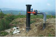
LFG extraction standard vertical well (Monte Umbriano, Italy) |